Offroad Trailblazers and Envoys

Home-Made Secondary Battery Setup

Any special projects involving a decent amount of fab work (bumpers, sliders, roof racks, etc)

by Trail X » Sat Dec 19, 2009 12:07 am

Back when I made my switch panel, I put a switch on there to control an auxiliary battery. It's taken me a while to get this project designed, ordered, assembled, and installed.

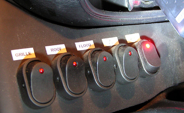
So lets start with the switch. The switch obtains 12V power only when the key is in the on position.

Image

The signal wire from the front switch then heads back under the rear seats... where the brains of the operation are.

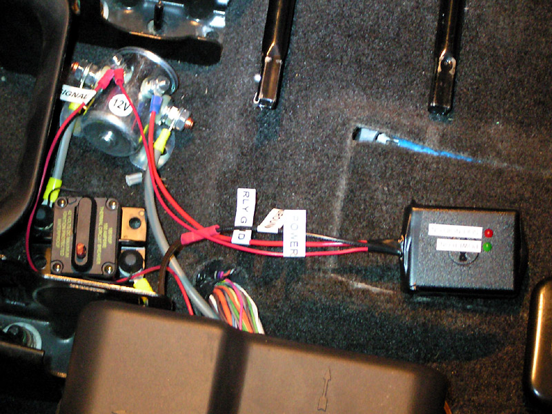
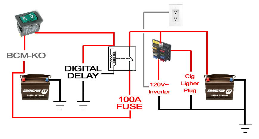
I'll try to give you a quick synopsis of what goes on back there. First of all, the charging current is pulled off of the rear main 12V pole. The charging wire, 8 AWG (rated for 15' of wire 100 Amps non-steady max), runs from the 12V pole, and first hits a 100 Amp, resettable breaker. From there, the charging power travels to a 100 Amp constant-duty solenoid. From there, the 12V hot wire travels onto the auxiliary battery.

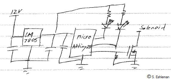
The signal wire, from the front switch, runs to the solenoid signal pole. Also getting 12V from this signal wire is my delay. This home-made digital delay waits 5 minutes before then connecting the ground side of the solenoid to ground through a FET rated for 1 amp continuous.

It's still a little messy, wire-wise... I'll clean it up with some wire-wraps eventually. But despite the messyness,... it works!

Image

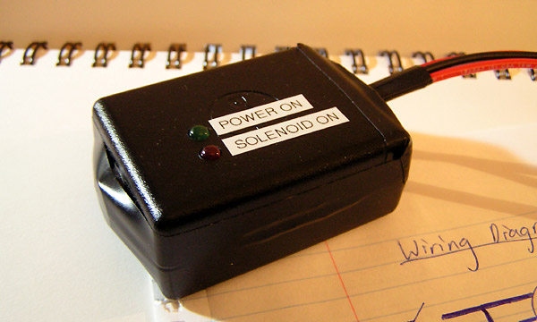
Close up of the digital delay (I used an old Dell power supply as the housing):

Image

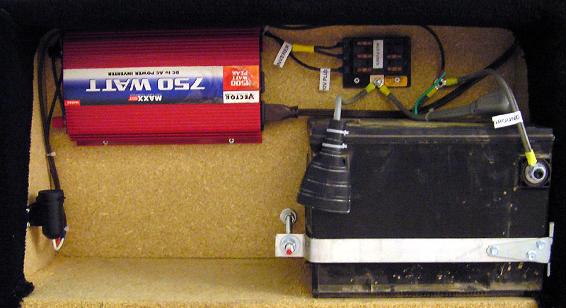
The power from the solenoid and a ground runs through a plug and into my rear cargo drawer enclosure, where I installed the aux battery. The rear battery has its own fuse box for the 750 Watt inverter and 12V lighter-plug (for future 12V cooler or fridge).

Picture when I finished it, not installed in the vehicle:

Image

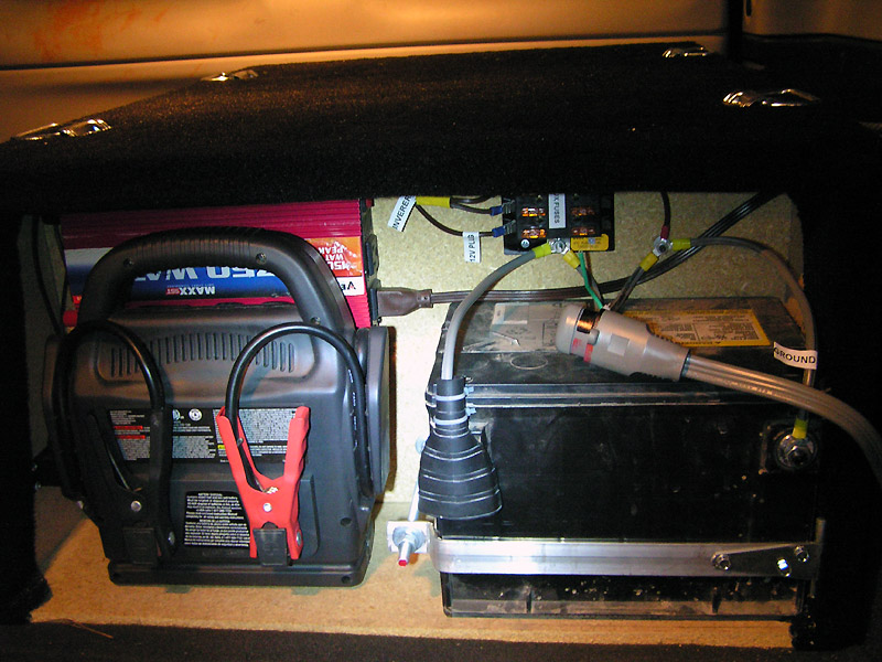
Picture installed in the vehicle, shows plug connection and location of emergency jump starter:

Image

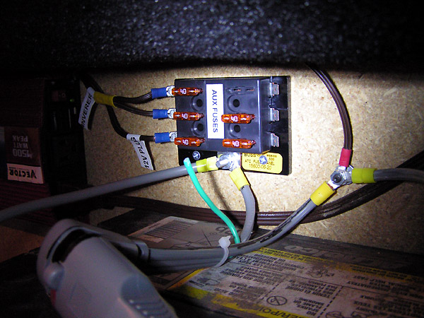
Close up of rear fuse box. Two 40 A fuses (the max I could find for a blade fuse) supply the inverter. The green wire sticking up is one I may use in the future... it's a potential signal wire running from the vehicle into the aux battery enclosure.

Image

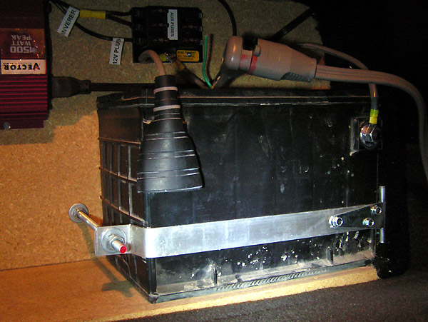
Close up of the battery and it's holding system I made:

Image

So, overall, I keep the switch in the on-position. After the engine is started, the alternator charges the primary battery back from starting. 5 minutes after starting, the rear battery begins charging. So far, the system seems to work great!

:safari:
8-) Build Thread | ExPo Build | YouTube Videos
Not all who wander are lost. -Tolkien
User avatar
Trail X
Founder
 
Posts: 9935
Joined: Mon Sep 07, 2009 10:22 pm
Location: VA, Roanoke
Name: James Downing
Vehicle Year: 2005
Vehicle: Chevrolet TrailBlazer
DriveTrain: 4WD w/ Aftermarket Locker
Rank: Expedition Guide

by Trail X » Sat Dec 19, 2009 12:08 am

Rough wiring diagram:

Image
User avatar
Trail X
Founder
 
Posts: 9935
Joined: Mon Sep 07, 2009 10:22 pm
Location: VA, Roanoke
Name: James Downing
Vehicle Year: 2005
Vehicle: Chevrolet TrailBlazer
DriveTrain: 4WD w/ Aftermarket Locker
Rank: Expedition Guide

by foosh » Sat Dec 19, 2009 12:09 am

Very cool what do you plan on using the extra power for?
Only White Lifted TB in Jerzey on 33's :safari:

:flex dirty: Pine Barrens Wheelin!
Build Thread http://forums.offroadtb.com/viewtopic.php?f=25&t=113
User avatar
foosh
Addict
 
Posts: 715
Joined: Fri Sep 11, 2009 9:01 pm
Location: Red Bank Area
Vehicle Year: 2004
Vehicle: Chevrolet TrailBlazer
DriveTrain: 4WD
Rank: Offroad Rated

by Trail X » Sat Dec 19, 2009 11:11 am

The whole point of the setup is that it disconnects when the engine is off. So I'll be able to constantly run a cooler/refrigerator, lights, and any A/C devices I want while at camp. After 5 minutes of running the truck, the brains will begin charging the camp battery.

Sorry, I should have made that more clear.
8-) Build Thread | ExPo Build | YouTube Videos
Not all who wander are lost. -Tolkien
User avatar
Trail X
Founder
 
Posts: 9935
Joined: Mon Sep 07, 2009 10:22 pm
Location: VA, Roanoke
Name: James Downing
Vehicle Year: 2005
Vehicle: Chevrolet TrailBlazer
DriveTrain: 4WD w/ Aftermarket Locker
Rank: Expedition Guide

by Philberto » Sat Dec 19, 2009 1:19 pm

Schematics? Circuit diagram?
My Build Thread | 2006 Trailblazer LS Desert Camping Edition **SOLD**
2013 Nissan Xterra S "ReXterra"
User avatar
Philberto
Lifer
 
Posts: 2046
Joined: Fri Sep 11, 2009 5:30 pm
Location: CA, Oxnard
Name: Philip Cruz
Vehicle Year: Other
Vehicle: Other Vehicle
DriveTrain: 4WD
Rank: Offroad Rated

by Trail X » Sat Dec 19, 2009 2:19 pm

I posted one to post #2, above. :shock:
8-) Build Thread | ExPo Build | YouTube Videos
Not all who wander are lost. -Tolkien
User avatar
Trail X
Founder
 
Posts: 9935
Joined: Mon Sep 07, 2009 10:22 pm
Location: VA, Roanoke
Name: James Downing
Vehicle Year: 2005
Vehicle: Chevrolet TrailBlazer
DriveTrain: 4WD w/ Aftermarket Locker
Rank: Expedition Guide

by Philberto » Sat Dec 19, 2009 2:58 pm

I meant for the digital delay... I can follow circuit diagrams, but just can't design my own.
My Build Thread | 2006 Trailblazer LS Desert Camping Edition **SOLD**
2013 Nissan Xterra S "ReXterra"
User avatar
Philberto
Lifer
 
Posts: 2046
Joined: Fri Sep 11, 2009 5:30 pm
Location: CA, Oxnard
Name: Philip Cruz
Vehicle Year: Other
Vehicle: Other Vehicle
DriveTrain: 4WD
Rank: Offroad Rated

by Trail X » Sat Dec 19, 2009 4:00 pm

I got a lot of help on that part from my buddy, who's a computer engineer. I know it had a micro controller that threw a 1 Amp FET (like a mini relay) after a 5 minute countdown. I can do analog circuits, but digital circuits aren't my forte. I was able to follow what we did, but I couldn't draw you a diagram.

The code was fairly simple though: Green LED on. Wait, 300 seconds. Red LED on. Send power to FET.

It was an 8 pin controller, and we only used Power, Ground, and 3 other pins.
8-) Build Thread | ExPo Build | YouTube Videos
Not all who wander are lost. -Tolkien
User avatar
Trail X
Founder
 
Posts: 9935
Joined: Mon Sep 07, 2009 10:22 pm
Location: VA, Roanoke
Name: James Downing
Vehicle Year: 2005
Vehicle: Chevrolet TrailBlazer
DriveTrain: 4WD w/ Aftermarket Locker
Rank: Expedition Guide

by Philberto » Sat Dec 19, 2009 4:23 pm

Hmm... time to seek out my electronic engineer friend... or maybe if I send Bill some beer, he can throw something together for me. Looking at getting 2 Diehard Platinums sometime next year, one to replace the old batt, and one to supplement.
My Build Thread | 2006 Trailblazer LS Desert Camping Edition **SOLD**
2013 Nissan Xterra S "ReXterra"
User avatar
Philberto
Lifer
 
Posts: 2046
Joined: Fri Sep 11, 2009 5:30 pm
Location: CA, Oxnard
Name: Philip Cruz
Vehicle Year: Other
Vehicle: Other Vehicle
DriveTrain: 4WD
Rank: Offroad Rated

by teebes » Sat Dec 19, 2009 5:23 pm

Good stuff! Home made projects rock (when they work) :D

Just make sure you flick off the secondary circuit before any winch pulls. Having to constantly reset the breaker would suck - most dual battery setups recommend no fuse w/ winches. Of course, the wiring would need an upgrade then, too.
User avatar
teebes
Founder
 
Posts: 1052
Joined: Thu Sep 03, 2009 1:05 am
Location: CA, San Diego
Name: Teebes
Vehicle Year: 2002
Vehicle: Chevrolet TrailBlazer
DriveTrain: 4WD w/ Aftermarket Locker
Rank: Expedition Rated

by bgwolfpack » Sat Dec 19, 2009 5:35 pm

Very Cool.

Something for us to study, thank you. ;)
bgwolfpack
Veteran
 
Posts: 1794
Joined: Fri Sep 18, 2009 7:19 pm
Name: Randy
Vehicle Year: Other
Vehicle: Other Vehicle
DriveTrain: 4WD

by Trail X » Sat Dec 19, 2009 6:20 pm

teebes wrote:Just make sure you flick off the secondary circuit before any winch pulls. Having to constantly reset the breaker would suck - most dual battery setups recommend no fuse w/ winches. Of course, the wiring would need an upgrade then, too.

Yeah, that was the main reason I put the switch on the system... It could have been wired without the switch, but I like having the added control.

The wiring I used cannot handle the current pull from the winch... so the breaker is kinda a nice, just in case I forget to turn the charging circuit off. :)

Plus... I learned early in life (the hard way) that I should fuse everything... electrical fires suck!
8-) Build Thread | ExPo Build | YouTube Videos
Not all who wander are lost. -Tolkien
User avatar
Trail X
Founder
 
Posts: 9935
Joined: Mon Sep 07, 2009 10:22 pm
Location: VA, Roanoke
Name: James Downing
Vehicle Year: 2005
Vehicle: Chevrolet TrailBlazer
DriveTrain: 4WD w/ Aftermarket Locker
Rank: Expedition Guide

by Gordinho80 » Mon Dec 21, 2009 3:26 pm

Very nice! Glad to see it finally put together and working. So I'm thinking February or March, you head out to NJ to set me up?
Mario - Build Thread
User avatar
Gordinho80
Lifer
 
Posts: 2787
Joined: Tue Sep 08, 2009 9:27 am
Location: NJ, Jackson
Name: Mario Almeida
Vehicle Year: Other
Vehicle: Other Vehicle
DriveTrain: 4WD

by Trail X » Mon Dec 21, 2009 4:05 pm

Philberto wrote:I meant for the digital delay... I can follow circuit diagrams, but just can't design my own.


I got my buddy to draw up the timing/delay circuit from memory (he warned it could be slightly off):

Image

The LM7805 is the voltage regulator, drops the 12V down to 5V for the micro.

LM7805:
Image

The micro is an Attiny25, 8 pin micro. Here's the specs of the Attiny10, 6 pin:
Image

The last part is the FET, basically a mini relay. Make sure this is rated to flow the amperage that your solenoid requires. Mine required just under 1 A.


Hopefully that helps you some.
8-) Build Thread | ExPo Build | YouTube Videos
Not all who wander are lost. -Tolkien
User avatar
Trail X
Founder
 
Posts: 9935
Joined: Mon Sep 07, 2009 10:22 pm
Location: VA, Roanoke
Name: James Downing
Vehicle Year: 2005
Vehicle: Chevrolet TrailBlazer
DriveTrain: 4WD w/ Aftermarket Locker
Rank: Expedition Guide

by bartonmd » Mon Dec 21, 2009 4:12 pm

James,

What you're using is called a PLD (programmable logic device)... They're cheap and available... We used them a lot in the lab, in my digital circuit design courses, and the programming software is free, but they do require a programming board that hooks to your computer... The ones we used were from Atmel, and they looked something like this: http://microcontrollershop.com/product_ ... cts_id=180

You can, however, do the same thing (without the lights) with a 5-minute Square-D time delay relay... Those are like $70 each, plus whatever the base costs, so if you're doing 1, that's great... If you're doing 2 or more, you might as well do the PLD thing...

There are infinite ways to do the same thing, though...

ETA: OK, now I see you posted while I was posting... A small microprocessor is basically the same thing as a PLD, but is programmed slightly different (at least the ones we had were)

For clarification, a FET is a "field effect transistor", and is basically an effecient, high current transistor (no relay contacts, but silicon that either blocks current, or lets it through, depending on what you're doing with the Gate... Also has a linear region in the middle, which will cause the thing to sink a lot of heat, so watch turning it half on or something). A lot of times, they look like the picture you posted of the 7805 voltage regulator (TO220 package)...

Mike
bartonmd
Moderator
 
Posts: 4469
Joined: Wed Sep 09, 2009 9:35 am
Location: IN, Indianapolis
Name: Mike
Vehicle Year: 2007
Vehicle: Chevrolet TrailBlazer
DriveTrain: 4WD w/ G80
Rank: Offroad Rated

by Trail X » Mon Dec 21, 2009 4:22 pm

The FET isn't really a relay, you're right, but for explanations-sake, it's a close likeness... at least to an ME.

The FET we used had a heat sink on it, we tested it for steady-state heat dissipation, and seemed fine in the lab.
8-) Build Thread | ExPo Build | YouTube Videos
Not all who wander are lost. -Tolkien
User avatar
Trail X
Founder
 
Posts: 9935
Joined: Mon Sep 07, 2009 10:22 pm
Location: VA, Roanoke
Name: James Downing
Vehicle Year: 2005
Vehicle: Chevrolet TrailBlazer
DriveTrain: 4WD w/ Aftermarket Locker
Rank: Expedition Guide

by bartonmd » Mon Dec 21, 2009 4:29 pm

JamesDowning wrote:The FET isn't really a relay, you're right, but for explanations-sake, it's a close likeness... at least to an ME.

The FET we used had a heat sink on it, we tested it for steady-state heat dissipation, and seemed fine in the lab.


Oh, they'll flow a ton of current when hard-on (hehe) without heating up, but if you're in the linear region of the control, and only letting half current through or something, the MOSFET is burning up the extra voltage inside itself, so it will get hot... You just need to make sure it's out of the linear region, and is passing almost the entire voltage/current through... If it did fine in the lab, then you're fine... This is very basic, and I'm sure if your friend can set up the PLD/micro, he can work the gate of at FET...

Mike
bartonmd
Moderator
 
Posts: 4469
Joined: Wed Sep 09, 2009 9:35 am
Location: IN, Indianapolis
Name: Mike
Vehicle Year: 2007
Vehicle: Chevrolet TrailBlazer
DriveTrain: 4WD w/ G80
Rank: Offroad Rated

by Philberto » Mon Dec 21, 2009 7:45 pm

I knew there was a reason I didn't try and become an electronic engineer... *pops 3 advil* Thanks for getting that rough schematic from your friend. I'll be trying that delay setup with a National Luna solenoid I think...
My Build Thread | 2006 Trailblazer LS Desert Camping Edition **SOLD**
2013 Nissan Xterra S "ReXterra"
User avatar
Philberto
Lifer
 
Posts: 2046
Joined: Fri Sep 11, 2009 5:30 pm
Location: CA, Oxnard
Name: Philip Cruz
Vehicle Year: Other
Vehicle: Other Vehicle
DriveTrain: 4WD
Rank: Offroad Rated

by Wahugg » Wed Feb 12, 2014 9:59 pm

Out of curiosity, how do you prevent the rear battery from discharging too far? Does the converter and fridge have an automatic cut off?

-Wahugg
Wahugg
Addict
 
Posts: 576
Joined: Fri Oct 07, 2011 10:09 am
Name: Wahugg
Vehicle Year: Other
Vehicle: Other Vehicle
DriveTrain: AWD w/ G80

by jhmeg2 » Thu Nov 27, 2014 3:44 am

When I added the 4 extra batteries for my audio, I just replaced the stock alternator with a 318 unit, ran 0-AWG from alt to 300 amp fuze to battery. Battery to 250 amp fuze, to the four batteries all iin parallel with 0-AWG. No relays no isolator. All worked fine.
2003 LTZ-3" suspension-3"body-Massive rear upper/lower-pan hard bar-Bilstien HD struts-Skyjacker 7000 shocks-Micky Thompson 15"W/-35-12.5-15 STT-Barton front bumper, oil and radiator skids-turbo mufler-And then theres the audio
User avatar
jhmeg2
Member
 
Posts: 68
Joined: Thu Aug 16, 2012 12:55 pm
Location: Wi. Hancock
Name: Patrick
Vehicle Year: 2003
Vehicle: Chevrolet TrailBlazer
DriveTrain: 4WD w/ G80

Next

Return to Fab Work

cron