Offroad Trailblazers and Envoys

DIY: Offroad Roof Light Bar

Breaker 1-9, anybody got a copy? Any discussion or mods relating to electrons and wires go here.

by Trail X » Mon Sep 07, 2009 11:20 pm

Image

The bar itself is all aluminum, with a flat black paint. I did not want to deal with rusting, so aluminum seemed to make sense.

Image

I mounted it so that it is easily removable. I made a plate that fits perfectly in the roof rack slot. Then I JB Welded a nut to the back side. It works like a charm. It was also very simple:

Image

I ran the wiring through the rear door. This made sense to me, since I did not want to drill through the roof yet (I've only had the truck for about 20 days).

I also wanted the rack to be easily removable. To do this, I ran the wiring to the inside top of the rear door. Then a simple plug comes out of the molding over the b pillar. This is where the lights plug in.

Image

You may recognize the lights as the same as the Roadie's. They are made by blazer, marketed as tractor lights. They are cheap lights but they have a good mounting system (it swivels all over the place). I did not want to spend a ton of money on this, so they were perfect for me. (plus I can update the bulbs later if I need to).

A view from the rear:

Image

And of course, a comparison beam shot. The great thing is that I can make them point anywhere I want, so this beam pattern is not set in stone.

Image

The overall cost was quite low. I spent maybe $100 on the entire setup. This includes lights, switches, relays, metal, bolts, sweat, & tears.

Next comes the how to.
8-) Build Thread | ExPo Build | YouTube Videos
Not all who wander are lost. -Tolkien
User avatar
Trail X
Founder
 
Posts: 9935
Joined: Mon Sep 07, 2009 10:22 pm
Location: VA, Roanoke
Name: James Downing
Vehicle Year: 2005
Vehicle: Chevrolet TrailBlazer
DriveTrain: 4WD w/ Aftermarket Locker
Rank: Expedition Guide

by Trail X » Mon Sep 07, 2009 11:24 pm

Parts List:

4 lights of your choice
4' - 3/4" square aluminum rod
2 bolts - 1.5" long
2 washers
2 nuts - same size as bolts
2 end-caps for your aluminum rod
2 1" x 3" x 1/16" aluminum sheet (with hole in it)
lots of wiring accessories (relay, switch, fuse, wire, connectors, plugs)

Tools:

JB Weld
can of flat black spraypaint
sheet of sandpaper
hacksaw
drill with drill bits for metal
wire stripper
wrench set
------------------------------------------
How-To:

Take the aluminum rod, and cut it slightly longer than your roof rack with the hacksaw. I believe I cut mine to be 44.5" (I cant remember exactly, but there was about .5" of overhang past the roof rack).

The next job is to drill the holes. I used the 1/4" bolts as the main vehicle connection bolt. So I accordingly drilled 1/4" holes in the aluminum support rod at the direct center of the roof rack (you will have to measure this also, sorry).

You have to drill the holes for the light's bolts next. I chose 11" spacing between lights, it seemed to work ok. My light bracket bolts were 3/8", check your size before drilling. I did not drill these holes on the same face of the aluminum rod however. I drilled these on the opposite face, that is how I made the 'low profile' look. That choice is up to you.

After cutting and drilling, it is time to paint. Go over the entire surface of the rod with some sandpaper. You want to rough up all surfaces so that you can get a good bond (get the edges too, don't just focus on the flat surfaces). You can paint it with primer first, or you can find paint made for metal.

While waiting for that to dry, make your attachment brackets. I made mine from 1"x 1/16" extruded aluminum sheet. I cut this into two 3" sections. The sections would then measure 1"x 3"x 1/16". I drilled a 1/4" hole in the center of each of these plates. You want to take a free bolt and nut, and attach that through the hole in this plate. Next take JB Weld, and put a small amount around the edge of the nut. This will basically weld your nut to the plate.

While this is drying, wire up your vehicle. I cannot give you exact directions here, but this should be fairly straight forward. I recommend using a relay, as most switches cannot handle the amperage associated with 4 lights.

After letting the paint and JB weld dry, attach your lights to the rod. These go in the 4 holes that were drilled 11" apart.

While this is on your workbench, it is time to wire it up. Do not wire them in series. You want to run two wires down your rod, and then attach the red wires of the lights to one wire, and the black wires to the other wire. I used heat-shrink around each of the wire junctions with a spot of silicon in the heat-shrink. This provides a pretty good seal for the electrical connections. I used some small zip-ties to attach the wire to the aluminum support rod.

Extend your wire 12" or so past the end of the rod, and put a two-pin plug at the end. Run this wire in the rear door. From your wiring package in the truck, run the associated power and ground wires up to the top of the B pillar. Put the other plug on the end of this line.

Its now time to mount your light bar. Insert the plates with the nuts into each side of the rack. Position the light bar over the plate, and insert your 1/4" bolt into the hole in the roof rack. Thread the bolt into the plate's hole. and tighten it where you want the light bar to be located.

The last step is plugging your lights in, and flipping the switch.
------------------------------------------
Here's a closeup of the wiring, nuts and light mounts. (JamesDub, the lights stick above the center of the roof by 5.5")
Image

Switch location. Left switch is the roof lights. Right switch is the red and white emergency lights. (the go-fast switch)
Image

Location of relay, power and ground sources. Under the rear seat.
Image

Location of the plug for the lightbar. That is the b pillar. View from rear seat.
Image

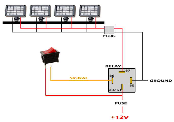
Quick wiring diagram.
Image

The roof rack mounting plates.
Image

Closeup of the plates when mounted in the roof rack.
Image
8-) Build Thread | ExPo Build | YouTube Videos
Not all who wander are lost. -Tolkien
User avatar
Trail X
Founder
 
Posts: 9935
Joined: Mon Sep 07, 2009 10:22 pm
Location: VA, Roanoke
Name: James Downing
Vehicle Year: 2005
Vehicle: Chevrolet TrailBlazer
DriveTrain: 4WD w/ Aftermarket Locker
Rank: Expedition Guide

by A-Train » Fri Oct 30, 2009 2:36 pm

thanx for the help james...about how much time was put into this mod...
I plan on putting a bar like this on my TB very soon...thanks
A-Train
Cruiser
 
Posts: 13
Joined: Thu Oct 22, 2009 12:38 pm
Location: Nolensville, TN
Vehicle Year: 2002
Vehicle: Chevrolet TrailBlazer
DriveTrain: 4WD

by bobbyblaze » Sat Oct 31, 2009 1:59 pm

Glad you brought this over from the OS. It's a great how-to. Well thought out and laid out. On my to-do list too.
Time. . .is my greatest enemy.
User avatar
bobbyblaze
Trail-Blazer
 
Posts: 343
Joined: Thu Sep 10, 2009 10:31 pm
Name: bb
Vehicle Year: 2002
Vehicle: Other Vehicle
DriveTrain: 4WD
Rank: Offroad Rated

by cbbryan » Sun Nov 01, 2009 11:52 pm

This took me about a day in total time from aquiring the materials tools to finished working light bar. Trying to use a new cordless drill that had never been charged took longer than the manual said so it took a few hours to drill through the aluminum tube after that it was easy.
User avatar
cbbryan
Trail-Blazer
 
Posts: 270
Joined: Tue Sep 22, 2009 2:26 pm
Location: MS, Amory
Name: Chris
Vehicle Year: 2005
Vehicle: Chevrolet TrailBlazer
DriveTrain: 4WD

by Trail X » Mon Nov 02, 2009 12:08 am

Nice, post up some pics when you have a chance!
8-) Build Thread | ExPo Build | YouTube Videos
Not all who wander are lost. -Tolkien
User avatar
Trail X
Founder
 
Posts: 9935
Joined: Mon Sep 07, 2009 10:22 pm
Location: VA, Roanoke
Name: James Downing
Vehicle Year: 2005
Vehicle: Chevrolet TrailBlazer
DriveTrain: 4WD w/ Aftermarket Locker
Rank: Expedition Guide

by cbbryan » Mon Nov 02, 2009 1:21 am

JamesDowning wrote:Nice, post up some pics when you have a chance!


Sorry, but I lost my camera. I never knew that you build site would turn into a forum so I never really took pictures of anything. Rest assured though that from now on I will do my best to document everything. Maybe even go back and show how I did some things; I think I wired mine differently, I'll have to check and post later.
User avatar
cbbryan
Trail-Blazer
 
Posts: 270
Joined: Tue Sep 22, 2009 2:26 pm
Location: MS, Amory
Name: Chris
Vehicle Year: 2005
Vehicle: Chevrolet TrailBlazer
DriveTrain: 4WD

by janesy86 » Thu Nov 12, 2009 3:53 pm

Quick question on wiring... :gimp:

I am planing on using 10 guage from the lights to the relay and have a 30amp 10 guage blade fuse holder. For the switch I can use a smaller guage wire correct?

And also I plan to ground the lights at the bolt that hold the roof rack rails to the body so i don't have to run it into the vehicle. So by doing this do I still need to run a ground wire from the relay to a grounding location in the vehicle as well?

Thanks in advance! :cheers:
Build Thread
Back to stock, had fun while it lasted...
janesy86
Veteran
 
Posts: 1291
Joined: Thu Sep 10, 2009 2:29 pm
Location: MA, Salem
Name: Nick Janes
Vehicle Year: 2007
Vehicle: Chevrolet TrailBlazer
DriveTrain: 4WD w/ G80
Rank: Offroad Rated

by Gordinho80 » Thu Nov 12, 2009 4:00 pm

Since the switch will use much less amperage, yes, the wire can be thinner.

The Lights can be grounded at the rail bolt, but its not the BEST ground to use. I had my lights grounded at one of those bolts before and it was fine...

The relay NEEDS to be grounded as well... JD's pic is great to demonstrate the proper wiring, I've also directed others with this image...

Image
Mario - Build Thread
User avatar
Gordinho80
Lifer
 
Posts: 2787
Joined: Tue Sep 08, 2009 9:27 am
Location: NJ, Jackson
Name: Mario Almeida
Vehicle Year: Other
Vehicle: Other Vehicle
DriveTrain: 4WD

by janesy86 » Wed Nov 18, 2009 1:40 pm

Man I wish I could say mine was easy...I can't figure out what I did wrong. All connection are tight and followed the diagram but no dice. :scratch: The switch has power, fuse is good, soldered the pigtails from the lights onto the power and ground wires fine.. just can't get them to turn on. Ugh.
Build Thread
Back to stock, had fun while it lasted...
janesy86
Veteran
 
Posts: 1291
Joined: Thu Sep 10, 2009 2:29 pm
Location: MA, Salem
Name: Nick Janes
Vehicle Year: 2007
Vehicle: Chevrolet TrailBlazer
DriveTrain: 4WD w/ G80
Rank: Offroad Rated

by Gordinho80 » Wed Nov 18, 2009 1:42 pm

Do you have a meter? Read the voltage at the light... see if anything is making its way there. Are you running a relay for power? If so, when you activate switch, is relay clicking on?
Mario - Build Thread
User avatar
Gordinho80
Lifer
 
Posts: 2787
Joined: Tue Sep 08, 2009 9:27 am
Location: NJ, Jackson
Name: Mario Almeida
Vehicle Year: Other
Vehicle: Other Vehicle
DriveTrain: 4WD

by janesy86 » Wed Nov 18, 2009 1:50 pm

I thought I had a meter somewhere but misplaced it so I'll have to get one...and yes I am using a relay and it clicks when I flip the switch.

Edit: I just noticed that your diagram and JD's have the grond wire and the switch wire on opposite.. Which is correct and does that make a difference?
Build Thread
Back to stock, had fun while it lasted...
janesy86
Veteran
 
Posts: 1291
Joined: Thu Sep 10, 2009 2:29 pm
Location: MA, Salem
Name: Nick Janes
Vehicle Year: 2007
Vehicle: Chevrolet TrailBlazer
DriveTrain: 4WD w/ G80
Rank: Offroad Rated

by The Roadie » Wed Nov 18, 2009 1:55 pm

Terminals 85 and 86 on the traditional automotive relay are symmetrical, and ground can be on either side. There are relays with a built-in diode for spike suppression, and those can only be hooked up one way, but those are different animals.
User avatar
The Roadie
Founder
 
Posts: 5011
Joined: Mon Sep 07, 2009 11:29 pm
Location: CA, Vista, San Diego County
Name: Bill Carton
Vehicle Year: 2004
Vehicle: GMC Envoy
DriveTrain: 4WD w/ G80
Rank: Expedition Guide

by Trail X » Wed Nov 18, 2009 2:42 pm

Where did you ground your lights? It's almost always the ground. I've found that even with a meter you can sometimes get a ground signal, but once you try to run 20 A through the ground, it won't flow. So you may want to try removing any paint under your grommet so it seats well.
8-) Build Thread | ExPo Build | YouTube Videos
Not all who wander are lost. -Tolkien
User avatar
Trail X
Founder
 
Posts: 9935
Joined: Mon Sep 07, 2009 10:22 pm
Location: VA, Roanoke
Name: James Downing
Vehicle Year: 2005
Vehicle: Chevrolet TrailBlazer
DriveTrain: 4WD w/ Aftermarket Locker
Rank: Expedition Guide

by janesy86 » Wed Nov 18, 2009 2:59 pm

Under the bolt that holds the roof rack on...it might not be the best but I beleive a few people are using the same ground? You obviously would suggest under the bolt for the seat, correct?
Build Thread
Back to stock, had fun while it lasted...
janesy86
Veteran
 
Posts: 1291
Joined: Thu Sep 10, 2009 2:29 pm
Location: MA, Salem
Name: Nick Janes
Vehicle Year: 2007
Vehicle: Chevrolet TrailBlazer
DriveTrain: 4WD w/ G80
Rank: Offroad Rated

by Trail X » Wed Nov 18, 2009 3:07 pm

Try turning the lights on and then moving your ground connector around. If you see your lights flash on once in a while, that's most likely your problem.
8-) Build Thread | ExPo Build | YouTube Videos
Not all who wander are lost. -Tolkien
User avatar
Trail X
Founder
 
Posts: 9935
Joined: Mon Sep 07, 2009 10:22 pm
Location: VA, Roanoke
Name: James Downing
Vehicle Year: 2005
Vehicle: Chevrolet TrailBlazer
DriveTrain: 4WD w/ Aftermarket Locker
Rank: Expedition Guide

by MrSmithsTB » Wed Nov 18, 2009 3:13 pm

I've found the best idea for grounding is to splice the individual grounds together and run a length of wire to a place you know is solid ground, instead of trying to make one where they fall.
back in the saddle
TB BUILD
User avatar
MrSmithsTB
Veteran
 
Posts: 1756
Joined: Thu Sep 10, 2009 2:28 pm
Location: EHT, NJ
Name: Bob
Vehicle Year: 2006
Vehicle: Other GMT360/370
DriveTrain: AWD w/ G80
Rank: Offroad Rated

by Gordinho80 » Wed Nov 18, 2009 4:38 pm

If your wires are ran up the B pillar, there are a couple of good ground points right on the pillar. I used the roof rail bolt successfully for some time with my previous set up. I'd start with a meter, put the + pin at the + wiring, - pin on a known good ground... see if you're getting 12+ at the wire.
Mario - Build Thread
User avatar
Gordinho80
Lifer
 
Posts: 2787
Joined: Tue Sep 08, 2009 9:27 am
Location: NJ, Jackson
Name: Mario Almeida
Vehicle Year: Other
Vehicle: Other Vehicle
DriveTrain: 4WD

by KE7WOX » Thu Nov 19, 2009 8:11 pm

Where did you get the aluminum sheet?
This is an aggressive post. You probably won’t like it. It is quite doubtful that you have the taste or sophistication to be able to appreciate a post of this quality and depth.

Build Thread
User avatar
KE7WOX
Veteran
 
Posts: 1226
Joined: Tue Sep 29, 2009 2:10 pm
Location: OH, Dublin (Columbus)
Name: Felipe G
Vehicle Year: 2004
Vehicle: Chevrolet TrailBlazer
DriveTrain: 4WD

by Philberto » Thu Nov 19, 2009 8:33 pm

Hey, quick question re: the wiring... What kind of amperage would I be looking at for 2 55-watt lights wired in parallel? Figuring for wiring... I have 12-ga stranded, and wondering if that'll be sufficient... If I did my math correctly, I'll be pulling approx 8.5 amps @12v.

-edit: I think I found my answer and will be fine, but please interject if you find my math is wrong or if you think I'll need thicker wire.
My Build Thread | 2006 Trailblazer LS Desert Camping Edition **SOLD**
2013 Nissan Xterra S "ReXterra"
User avatar
Philberto
Lifer
 
Posts: 2046
Joined: Fri Sep 11, 2009 5:30 pm
Location: CA, Oxnard
Name: Philip Cruz
Vehicle Year: Other
Vehicle: Other Vehicle
DriveTrain: 4WD
Rank: Offroad Rated

Next

Return to Electrical / Radios