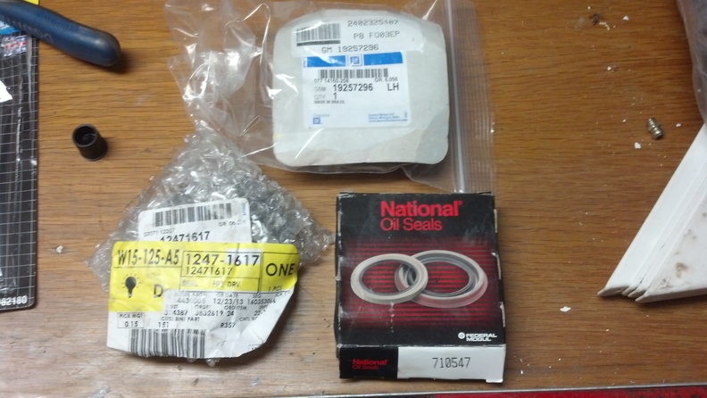
The seals needed for this job are as follows (I'd recommend getting all 3, the only seal possibly reusable is the pinion seal, but it's probably leaking anyways):
National Oil Seal #: 710547
GM Part #: 19257296
GM Part #: 12471617
Step 1:
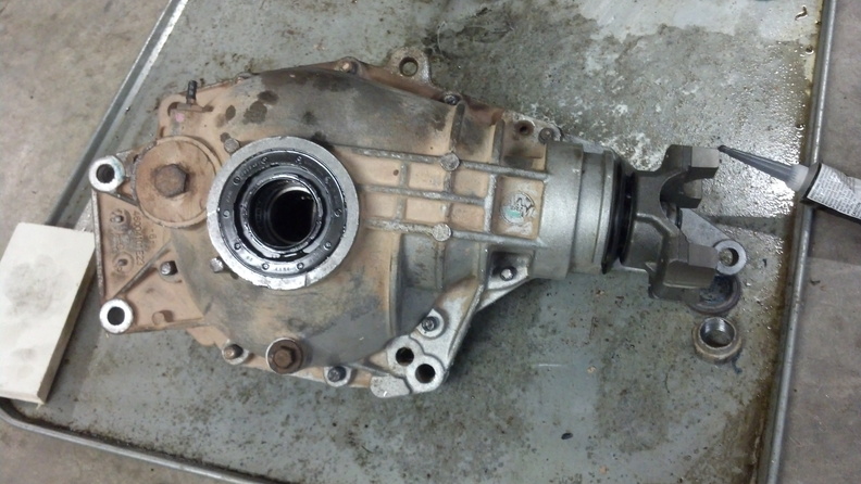
Tear down diff
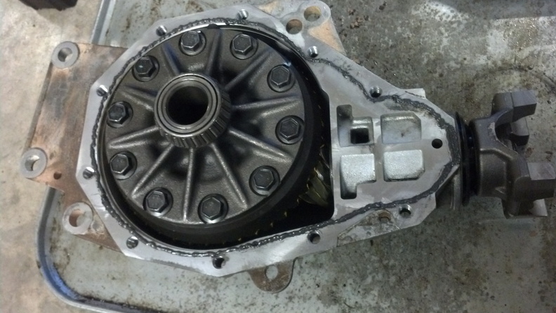
- 10 bolts on outside of case opens the halves (15mm).
- Lift the ring gear and carrier out of the diff.
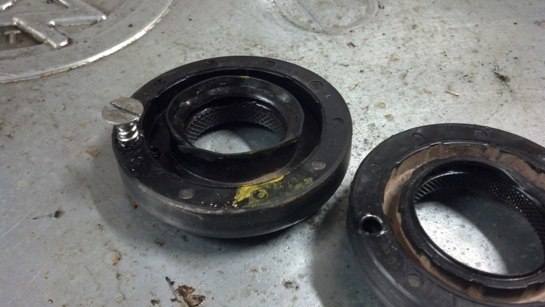
- Remove the seals from the left and right halves (I've found that the right sized screw driven into a pilot hole will stick pretty well, then I just pry on that with a hammer.)
- Remove the ten bolts holding on the ring gear. These are labeled as left hand thread in the service manual, but after wringing some bolt heads off, they are NOT. They are standard right-hand-threads.
- The ring gear is pressed onto the carrier, you can remove it by placing the carrier in a vice with the ring gear down, and working around the perimeter of the ring gear (on the beveled edge) with a screw driver and hammer. Be sure not to mess up the carrier's flange.
- Next remove the pinion. It will take a lot of torque to remove the nut (1-1/4" I believe). Hold the gear teeth of the pinion with your hand (use a towel as a barrier - don't grab it bare-handed!) and wring the nut off with a big impactor.
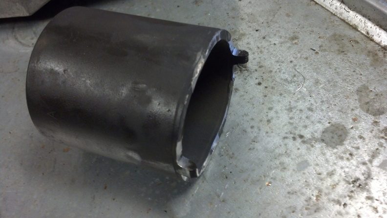
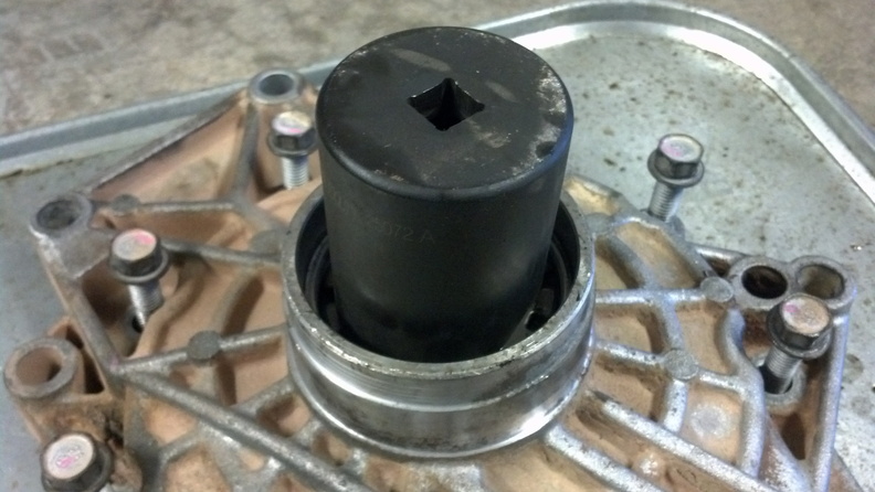
- You need a two-jaw puller to pull the U-joint yolk off of the pinion.
- Now you have to pound the pinion out of the rear bearing. I ended up having to practically stand on the diff housing half, and pound on the pinion end with a hammer. Put a towel inside the housing so that the pinion has something soft to hit when it eventually rockets out of the bearing.
- Take a bearing splitter to pull the forward pinion bearing off of the pinion.
- Get plenty of carb cleaner, and go to town and clean it up.
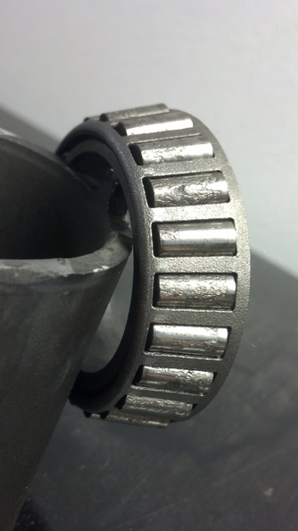
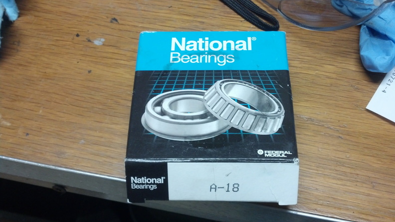
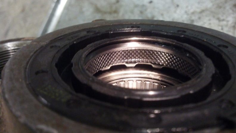
- Inspect for any bad bearings and replace as needed. The below example was on the engine-side on both differential carriers I've built so far, and seems somewhat common. This is a type A-18 bearing.
Step 2:
New ring gear
- To get the new ring gear on the carrier, you will need to heat up the new ring gear in your oven to about 400 degrees.
- With the carrier resting on a stable surface, set the hot ring gear in place, and begin threading the ring gear bolts in. Get them all started by hand, lightly synch down a couple of them. Tighten them down in a star pattern.
- Flip the carrier over, and immediately torque the 10 ring gear bolts to 55 ft-lbs.
Step 3:
New pinion
- The pinion requires the forward tapered roller bearing to be pressed onto the pinion shank. This generally requires a shop press. An old bearing race can work well to press on the bearing. Be sure not to press on the bearing cage. Don't forget to put the shim on the pinion before the bearing. The same shim that was on the old pinion gear is a good place to start here. It's also recommended to lubricate the pinion shaft where the press will occur.
- You can get a new crush sleeve, or you can take the old one place it over a pipe, and hammer the bent portion toward the pipe a bit. You want a slight amount of height elongation of the sleeve all the way around the sleeve. This will reduce the reassembly torque required on the pinion. Install the sleeve on top of the forward pinion bearing.
- Lubricate the pinion shaft above the sleeve, oil the bearing rollers, and place the pinion and sleeve back into the differential housing. The rear bearing will still be in there unless you removed the rear seal (might be a good idea to do now, since it's all apart). You will have to utilize the yolk and the pinion nut to press the rear bearing down the pinion shaft.
- Continue torquing the nut until some resistance to spin is present. Check the resistance with an in-lb torque wrench.
- The rotating torque of the pinion alone should be 10-20 in-lb for used bearings, or 15-30 in-lb for new. Be sure to rotate the pinion a few times to ensure the bearings have properly seated.
- Honestly, you will need to torque the pinion down again later, once you seal up the yolk, so you can be good with 5 in-lb for now and it will make reading backlash easier.
Step 4:
Backlash
- If you took the side adjusters out, or they had rotated before and were loose in the housing when you disassembled, then you need to start from square 1, otherwise you will at least have a good starting place.
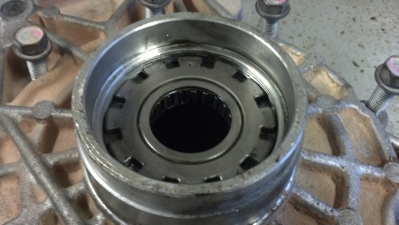
- If the adjusters were removed, you need to start by inserting them a few rotations into the housings. Keep in mind that the adjuster with the smaller needle bearing goes on the engine side of the diff. Don't forget to also install the bearing races inside the adjusters. The races set into bores on the inside of the adjusters, and can be fitted into place by hand (its easier if you slightly twist the bearing races while you insert them).
- If you have no load on the adjusters, you can spin them by hand, but if you are adjusting them with preload on them (while assembled), you will need a way to spin them. A drift and hammer may work, but you will bitch up the adjusters. I modified one for a DANA 40 by grinding off the other prongs, hammering the non-pinned sides together, and grinding down the prongs a bit. But if you're willing to loosen the halves of the diff whenever you need to make adjustments, you don't need one of these.
- Assemble the diff, including the carrier. You don't have to torque the case bolts yet, just get them nicely snug and ensure there is no gap between the halves of the diff. Snug them down in a star pattern.
- If you have not removed your adjusters, you can just go straight to checking backlash.
- If you are starting at square 1, you need to first start by turning the ring-side adjuster in until the ring gear bottoms out on the pinion. Mark the position of the adjuster (one of the adjuster's legs has a dimple in it). Now turn the ring gear side adjuster out two notches (one notch is supposed to equal .003" of backlash).
- Next, run the other side adjuster in until you can't anymore. Then tighten it one more notch to preload the carrier. Use the adjuster tool for this last notch, or loosen the case bolts, adjust it in, and then tighten them again.
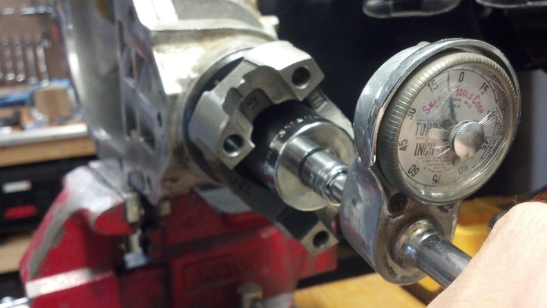
- Now it's time to check your current backlash. In general terms, the backlash is the free movement of the ring gear with the pinion gear fixed in place. However, with the 7.2" IFS design, you can't get an indicator on the gear teeth when the case is closed. So we check on the pinion yolk, as shown below. I didn't have a good arm to use, so I had to pile up some random items and tape the indicator down to prevent movement. It worked surprisingly well.
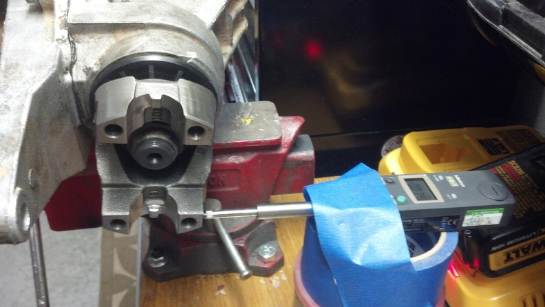
Assuming the pinions preload is low enough, feeling the backlash is pretty easy, there is a bit of rotational freedom in the pinion before you hear and feel it hit the ring gear teeth. Rotate the yolk to one side, zero your indicator, then rotate the pinion yolk to the other side. Divide the indicator reading by 2, and you have your backlash number. (You only have to divide by 2 in this situation because you're measuring off of the pinion yolk. - The spec for the backlash is .003"-.010", with a desirable range of .005"-.007".
- If you have too much backlash, you will need to bring the ring gear closer to the pinion by screwing the engine side adjuster in, and the other adjuster out. The backlash changes approximately .003" per notch of adjuster movement. Move them both an equivalent number of notches.
- If you have too little backlash, or the gears are bound up and will not move, you need to move the ring gear side adjuster out, and the other adjuster in.
- Once the backlash is adjusted, check the rotating torque of the pinion and carrier. Check it the same way as checking the pinion. The spec for the entire assembly is 15-30 in-lb (but ensure it is slightly more than the pinion alone to ensure there is some amount of preload on the carrier).
- If you need more preload, turn both adjusters in equally in small increments, and vice versa.
Step 5:
Gear Mesh
- We're not out of the woods just yet. We need to check to ensure that the gear teeth are meshing in the proper locations.
- Disassemble the case, or open up the fill hole, and begin painting the ring gear teeth (both sides, drive and coast) with yellow gear marking compound. Get at least 5 teeth in a group, in 3 groups around the ring gear.
- Now spin the pinion around a few times in both directions. You can use a drill at slow speed if you wish.
- Inspect the pattern that is left on both the gear and the coast sides of the ring gear teeth.
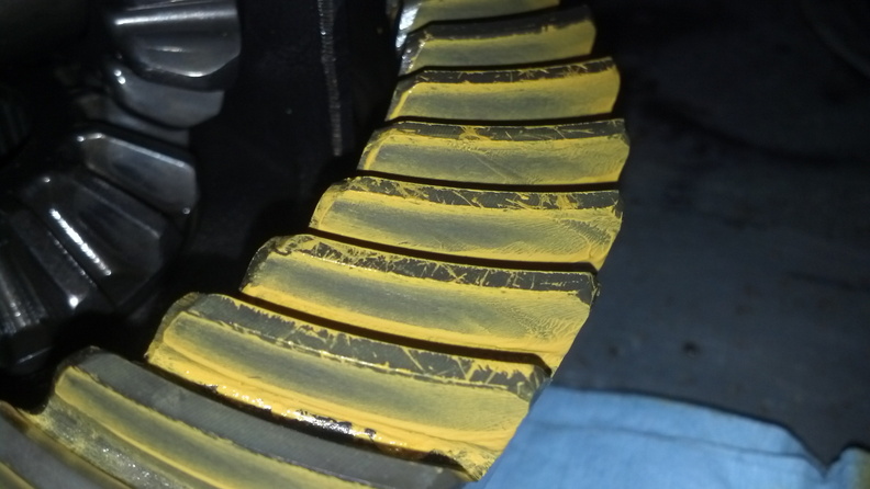
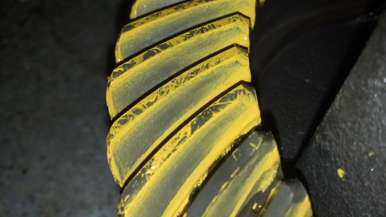
Compare the patterns to the manufacturer's recommendations, as provided in the manufacturer's booklet. You may need to re-do everything if the pattern does not align properly, but luckily there seems to be a lot of leeway here - at least by Yukon. - If you're good, then you're all set, otherwise do as the manufacturer's instructions say to do, and start the process over.
Step 6:
Final Reassembly
- Once you're happy with the specs that you've gotten, its time to do the final assembly. The first step of that is to disassemble the case halves, and take the yolk off of the pinion.
- If you are replacing the pinion seal (recommended) now is the time to install it.
- Oil the yolk's seal surface, and reassemble the yolk onto the pinion, but be sure to squirt some ultra-black RTV onto the splines to ensure an oil-tight seal. I also put a thick bead under the pinion nut's washer.
- Tighten the pinion nut down again, and once again check for the proper rotational torque of the pinion. Creep up on it in short bursts from your impactor. Get it into the range specified above.
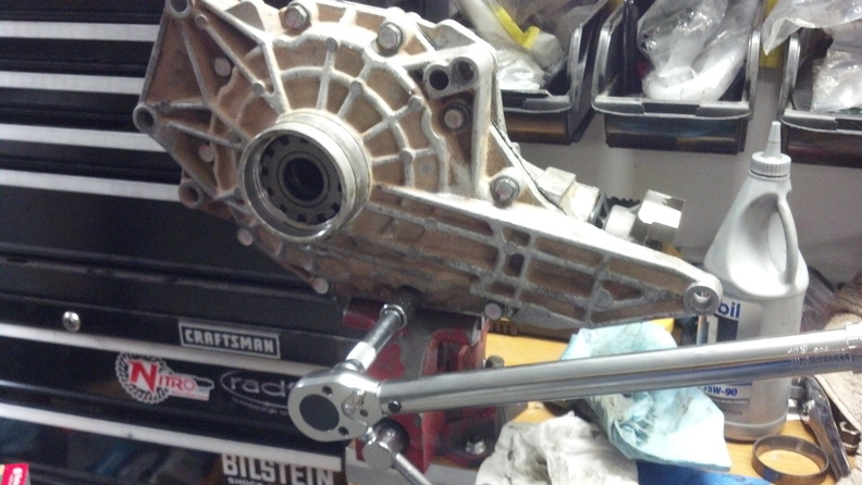
- Drop the carrier down into the pinion half of the diff, and put a nice bead of RTV around the cavity side of the gasket surface:
- Reassemble the other half of the carrier, and torque the case bolts down to 35 ft-lb.
- Perform one last check on the preload of the pinion and carrier, and then double check the backlash again (ok - you can skip this if you want, but I checked it a few more times).
- The last step is installing the seals over the adjusters. I used a small block of wood and a hammer and worked it around the seal edge in a star pattern.
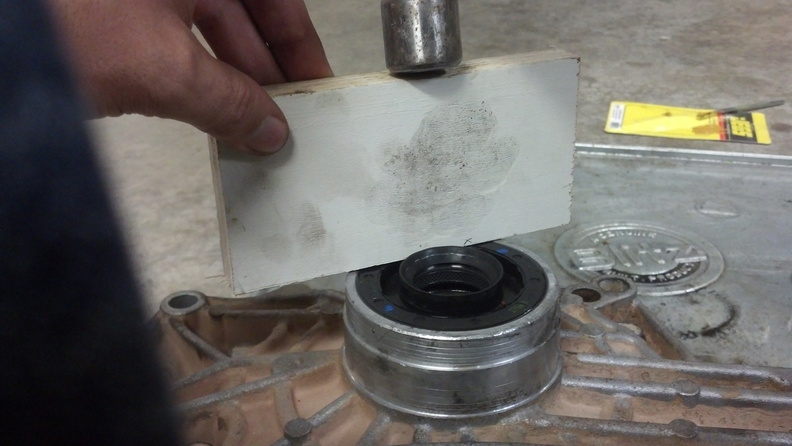
- I always like to check to ensure that there are at least two tangs of the seals that properly engaged with the adjusters (you don't want them to spin). At this point, you're ready to install the diff in the truck.
- Once its installed, DON'T FORGET TO ADD THE OIL!
I hope this helps. Please ask any questions you may have - or post up your patterns and share - I'll try my best to answer them.


 Viewed 37000 times")