-------------------------------------------------
General Operation:
The New Venture Gear model NVG 226 transfer case is a two speed automatic, active, transfer case. It provides five modes of operation: Auto 4WD, 4 HI, 4 LO, 2 HI and Neutral.
The Auto 4WD position allows the capability of an active transfer case, which provides the benefits of on-demand torque biasing wet clutch and easy vehicle tuning through software calibrations. The software calibrations show more features such as flexible adapt ready position and clutch preload torque levels. The technology allows for vehicle speed dependent clutch torque levels to enhance the performance of the system. For example, the system is calibrated to provide 0-5 lb ft of clutch torque during low speed, low engine torque operation, and predetermined higher torque for 20mph and greater. This prevents crow-hop and binding at low speeds and provides higher torque biases at higher vehicle speeds, to enhance stability.
The NVG 226 requires no clutch shimming. the transfer case control module controls for the wear of the clutch and different clutch torque levels. The software learns adapt ready positions, which are for the correct clutch torque. The learned adapt ready positions vary as the unit wears over its life.
2WD
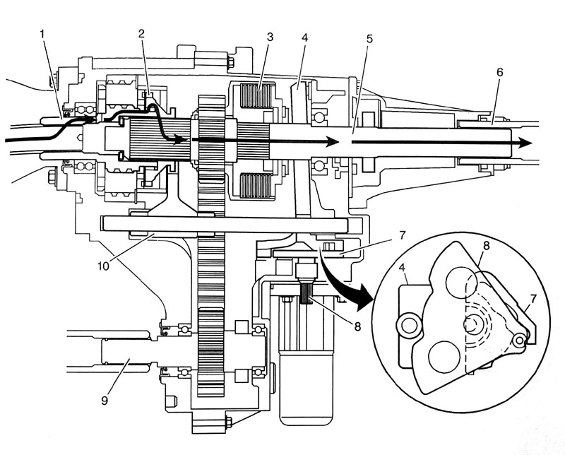
When the NVG 226 is in the 2 HI mode, the power flows from the transmission to the input shaft gear (1). The input shaft gear is connected to the rear output shaft (5) by the high/low range collar (2). The range collar inner teeth, high speed, are engaged with the input shaft gear (1) high speed position teeth. At the same time the range collar is slip splined to the rear output shaft (5). The rear output shaft delivers the power flow to the rear propshaft (6). The position of the control actuator lever shaft (8) allows no clutch engagement. The shift detent lever (7), which moves the shift rail and shift fork (10), is in the high speed position on the control actuator shaft (8).
4 HI and A4WD
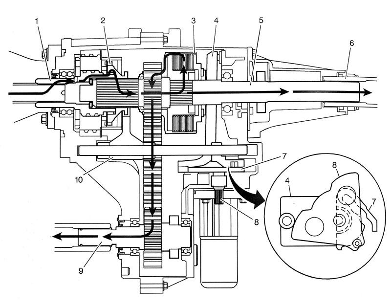
In the 4 HI mode, the power flow to the rear propshaft is the same as in the 2 HI mode. To deliver power flow to the front propshaft during the 4 HI position, the transfer control module commands the encoder motor to apply the clutch to a calibrated torque. the encoder motor turns the control actuator lever shaft (8). A brake in the encoder motor holds the control actuator shaft in the full clutch position. The control actuator lever shaft (8) is cam designed and the cam action moves the clutch lever (4). The clutch lever (4) pivots on the control lever picot studs and moves towards the clutch apply plate, to engage the clutch. As more pressure is applied to the clutch apply plate, the clutch disks are compressed. Using inner clutch disks, which are engaged with the clutch hub (3), and the outer clutch disks, which are engaged with the clutch housing, the power flow is delivered to the clutch housing.
The clutch hub (3) is splined to the rear output shaft (5), and the clutch housing rotates on a needle bearing on the rear output shaft (5). The chain drive sprocket is splined to the clutch housing. The power flows from the drive sprocket, through the chain, to the chain driven sprocket. The driven sprocket is splined to the front output shaft (9). The power flow is delivered to the front propshaft through the front output shaft (9).
During the Auto 4WD mode, the power flow is the same as it is in the 4 HI mode. Except during the A4WD mode, the encoder motor rotates the control actuator shaft lever to the learned adapt ready positions. Rotating the control actuator to the carious positions changes the clutch torque level. When a differential of front propshaft and rear propshaft speed is recognized, the transfer case control modules commands for more, or less clutch torque.
4 LO
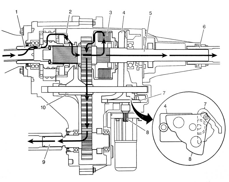
When shifting the transfer case to the 4 LO mode, it commands the encoder motor to turn the control actuator lever shaft (8) to move the shift detent lever (7), and to apply the clutch. The shift detent lever (7) moves the shift rail and the spring dampened shift fork (10). The shift fork (10) moves the high/low range collar (2) on the rear output shaft (5) splines toward the rear of the transfer case. The range collar (2) inner teeth, high speed, disengage from the input shaft gear (1) high speed teeth. The range collar (2) outer teeth, low speed, then engage in the planetary carrier teeth. The power flow is now from the input shaft (1) planetary teeth to the planetary gears in the carrier. Rotating the planetary gears, which are engaged in the annulus gear, the carrier rotates. The carrier, that is engaged to the range collar, then drives the rear output shaft. Therefore, providing a 2.69:1 reduction to the speed of the rear output shaft. The power flow to the front propshaft is the same as it is in the 4 HI mode.
A neutral position is obtained when the range collar is not engaged to the input shaft gear or the planetary carrier. Neutral position is used for towing the vehicle.
-----------------------------------------------
I hope this helps explain the transfer case internals. I wanted to share this excerpt with you because I found it extremely helpful in understanding how the NVG 226 internals operated! I'll also link to this thread from my site so it's easily located in the future.